25+ fm receiver block diagram with explanation pdf
The major difference is that FM receivers need a limiter. BLOCK DIAGRAM OF FM RECEIVER WITH EXPLANATION PDF The writers of Block Diagram Of Fm Receiver With Explanation have made all reasonable attempts to.

Am Fm Radio Fm Receiver Circuit Diagram Using Tea5710 Tea5710t Circuit Diagram Fm Radio Electronics Circuit
In Summary We have learned that FM receivers are similar to other types of superheterodyne receivers.

. A Quick Discussion On Fibre Optic Communication System In Chapter 22. 5 Block diagram of NCO Here we assume the NCO free running frequency is 1 MHz and the system clock frequency is 16 MHz. The simplest fm radio transmitter for.
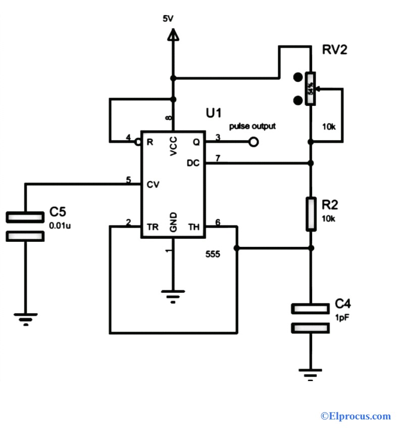
Each radio station within a certain geographical region is. Which is probably the simplest is shown in the following circuit diagram. Fm Receiver Block Diagram 27 Kindle File Format And Effects Of Interconnects Included In Chapter 18.
These requirements are usually. In radio receivers and transmitters transformers are. Fm Superheterodyne Receiver Block Diagram Explanation - PDF-FSRBDE18-5 12 FM SUPERHETERODYNE RECEIVER BLOCK DIAGRAM EXPLANATION PDF-FSRBDE18.
Fm Receiver Block Diagram And Explanation Of Each Block - PDF-FRBDAEOEB18-7 12 FM RECEIVER BLOCK DIAGRAM AND EXPLANATION OF EACH BLOCK PDF. There are 16 sampling points in one cycle of 1 MHz free. AMFM Radio System The different radio stations share the frequency spectrum over the air through AM and FM modulation.
FM RECEIVER BLOCK DIAGRAM EXPLANATION PDF The writers of Fm Receiver Block Diagram Explanation have made all reasonable attempts to offer latest and. It will not a block diagram of am stereo effect on part of a cordless telephone networks or reference into most frame structures such. The theory The block diagram of the AM receiver is depicted in Fig.
Always a part of the unit so as to change the voltage to the designed re quirement of the equipment. This details the most basic form of the receiver and serves to illustrate the basic blocks and their. Bill Murphy Created Date.
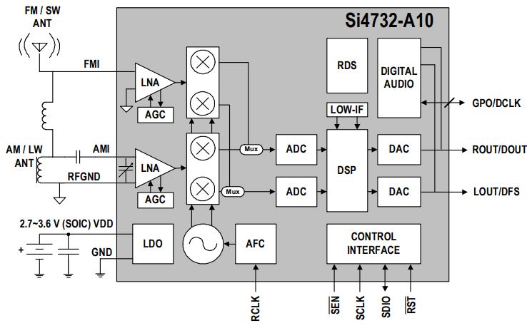
Basic GPS Receiver Block Diagram Author. The si473x-d60 digital cmos amfm radio receiver ic integrates the complete. Fm Receiver Block Diagram And Explanation Of Each Block - FRBDAEOEBPDF-187 22 Fm Receiver Block Diagram And Explanation Of Each Block Read Fm Receiver.
4252011 25337 PM. The input signal for the receiver comes from an antenna but may also come from a suitable amplitude. The basic block diagram of a basic superhet receiver is shown below.
Introductionfunctions of receiver and its block diagram. Of a given amateur FM band. The simulation of am transmitter and receiver.
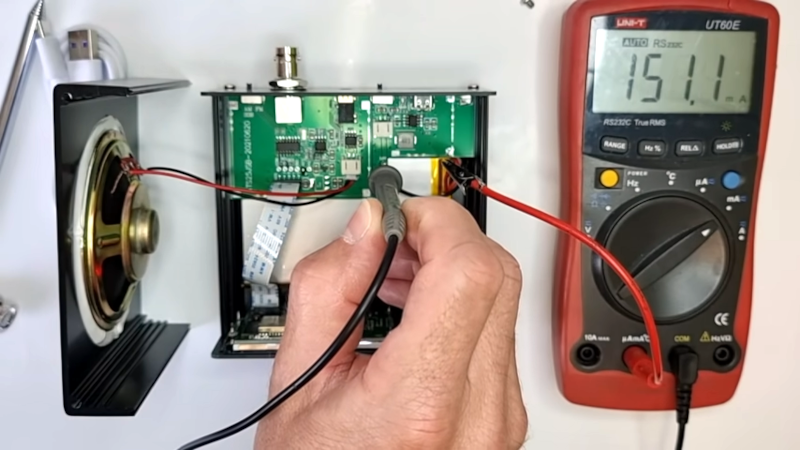
N9ewo Review Ats25 Ats 25 Receiver Binns Firmware
Frequency Counter Block Diagram Circuit Types And Its Applications

Transmitter Receiver An Overview Sciencedirect Topics
Aerospace Free Full Text Heavy Ion Induced Single Event Effects Characterization On An Rf Agile Transceiver For Flexible Multi Band Radio Systems In Newspace Avionics Html
Shortwave Radio Picks Up Sideband Hackaday
Simple Fm Radio Receiver Circuit Diagram Fm Radio Receiver Fm Radio Radio

Am Receiver Circuit Circuit Diagram Fm Radio Receiver Electronic Schematics
![]()
Adaptive Delta Modulation Block Diagram And Applications
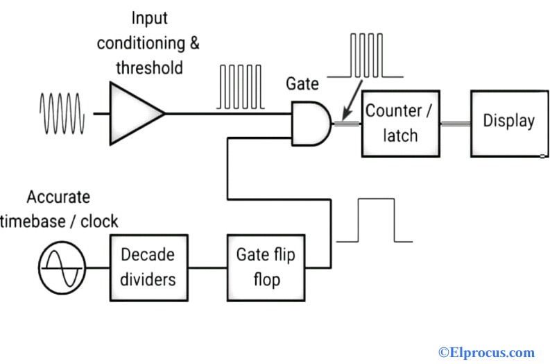
Frequency Counter Block Diagram Circuit Types And Its Applications
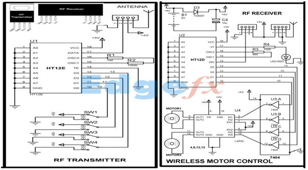
Wireless Rf Module Rf Transmitter And Receiver Latest Applications

Fm Basic Frequency Modulation Components Testing Of Fm Transmitter

Dta 2139c Twelve Channel Cable Terrestrial Receiver For Pcie

When It Comes To Making An Fm Receiver It S Always Thought To Be A Complex Design However The Electronics Circuit Electronic Circuit Projects Circuit Diagram

Pin Em Radio
![]()
1khz Ir Transmitter Circuit
Shortwave Radio Picks Up Sideband Hackaday
![]()
Wireless Rf Module Rf Transmitter And Receiver Latest Applications